Geometry ‚حŒ`ڈَ‚جڈî•ٌ‚ج‚ف‚ًژ‚؟پCPath‚حGeometry‚ج‘¼‚ةپCStroke, Fill ƒvƒچƒpƒeƒB ‚âƒCƒxƒ“ƒg‚ًژ‚آپB
Path ‚ج DataƒvƒچƒpƒeƒB‚ة Geometry ‚ًژw’è‚·‚邱‚ئ‚ة‚و‚èپCPath‚حˆêگl‘O‚جƒRƒ“ƒgƒچپ[ƒ‹‚ة‚ب‚éپB
| LineGeometry | ‚±‚ê‚ç‚حپCShape‚جLine, Rectangle, Ellipse ‚ئ“¯—l‚جŒ`ڈَ‚ً•\‚·پB ‚½‚¾‚µپCShape‚حپCPath‚ئ“¯—l‚ةپCStroke, Fill, Margin ‚ب‚ا‚ج ƒvƒچƒpƒeƒB‚ًژ‚آ‚ھپCGeometry‚حŒ`ڈَ‚جڈî•ٌ‚ًژ‚آ‚¾‚¯‚إ‚ ‚éپB |
| RectangleGeometry | |
| EllipseGeometry | |
| GeometryGroup | •،گ”‚ج Geometry ‚ًچ‡‚ي‚¹‚½ Geometry ‚ً—^‚¦‚éپB |
| CombinedGeometry | ‚Q‚آ‚ج Geometry ‚ً‰‰ژZ‚µ‚ؤپCگV‚µ‚¢ Geometry ‚ً—^‚¦‚éپB |
| PathGeometry | •،گ”‚ج”Cˆسگ}Œ`(PathFigure)‚إ Geometry ‚ً—^‚¦‚éپB |
| StreamGeomerty | ƒ~ƒjŒ¾Œê‚ًژg—p‚µ‚ؤ Geometry ‚ً—^‚¦‚éپB |
| Line | Shape |
<Line Stroke="Red" X1="0" Y1="0" X2="200" Y2="100"></Line> |
| Geometry |
<Path Stroke="Red">
<Path.Data>
<LineGeometry StartPoint="0,0" EndPoint="200,100"></LineGeometry>
|
|
| Rectangle | Shape |
<Rectangle Stroke="Red" Fill="Beige" Width="200"
      Height="100" ></Rectangle>
|
| Geometry |
<Path Stroke="Red" Fill="Beige">
    <Path.Data>
        <RectangleGeometry Rect="0,0,200,100"></RectangleGeometry>
    </Path.Data>
</Path>
|
|
| Ellipse | Shape |
<Ellipse Stroke="Red" Fill="Beige" Width="200" Height="100" ></Ellipse> |
| Geometry |
پEپEپE
<EllipseGeometry RadiusX="100" RadiusY="50" Center="100,50"></EllipseGeometry>
پEپEپE
|
‚±‚ê‚ç‚R‚آ‚جGeomerty‚حپC’P“ئ‚ب‚çShape‚ًژg‚¦‚خ‚و‚¢‚ھپCˆب‰؛‚ج‚و‚¤‚ة‘g‚فچ‡‚ي‚¹‚ؤژg‚¤ڈêچ‡‚ةˆس–،‚ھ‚ ‚éپB
<Path Stroke="Orange" Fill="Beige" Margin="10">
    <Path.Data>
        <GeometryGroup>
            <RectangleGeometry Rect="0,0,200,100"></RectangleGeometry>
            <EllipseGeometry RadiusX="50" RadiusY="30" Center="100,50"></EllipseGeometry>
        </GeometryGroup>
    </Path.Data>
</Path>
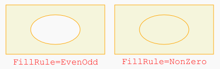
GeometryGroup ‚جٹù’è‚ج FillRuleƒvƒچƒpƒeƒB‚ح EvenOdd ‚إ‚ ‚èپC‘ب‰~‚ج“à•”‚ح“§–¾‚إ‚ ‚éپB
<GeometryGroup FillRule="Nonzero">پ@‚ئ‚·‚é‚ئپC‰؛گ}‰E‚ج‚و‚¤‚ة‚ب‚éپB
GeometryGroup ‚حپC”Cˆس‚جŒآگ”‚جGeometry‚ًƒOƒ‹پ[ƒv‰»‚·‚邱‚ئ‚ھ‚إ‚«‚éپB
GeometryGroup‚جچىگ¬‚ًƒRپ[ƒh(C#)‚إچs‚¤‚ة‚حپCˆب‰؛‚ج‚و‚¤‚ةڈ‘‚پB
GeometryGroup gg = new GeometryGroup();
gg.Children.Add(
    new EllipseGeometry(new Point(100, 50), 50, 30)
);
GeometryGroup‚ً Windows.Resources ‚ة“oک^‚µ‚ؤ‚¨‚«پCPath.Data ‚إ‚»‚ج–¼‘O‚ًژw’è‚·‚é‚·‚邱‚ئ‚ة‚و‚èپC”Cˆس‚جڈêڈٹ‚إ‰½“x‚إ‚àژg—p‚·‚邱‚ئ‚à‚إ‚«‚éپB
<Window پEپE >
<Window.Resources>
<GeometryGroup x:Key="Geometry1">پEپE</GeometryGroup>
</Window.Resources>
پEپEپE
<Canvas>
<Path Stroke="Blue" پEپE Data="{StaticResource Geometry1}"></Path>
</Canvas>
CombinedGeometry ‚حپC‚Q‚آ‚جGeometry پiGeometry1 ‚ئ Geometry2 ƒvƒچƒpƒeƒBپj‚ة‘خ‚µ‚ؤپCˆب‰؛‚ج‚¢‚¸‚ê‚©‚ج‰‰ژZ‚ًچs‚ء‚½Geometry‚ً—^‚¦‚éپB
| Union | ‚Q‚آ‚جGeometry‚جکa (G1 OR G2) |  |
| Intersect | ‚Q‚آ‚جGeometry‚ج‹¤’ت•”•ھ (G1 AND G2) |  |
| Xor | ‚Q‚آ‚جGeometry‚جXOR (G1 XOR G2) |  |
| Exclude | ‚Q‚آ‚جGeometry‚جچ· (G1 - G2) |  |
<Path Stroke="Orange" Fill="Beige" Margin="10">
    <Path.Data>
        <CombinedGeometry GeometryCombineMode="Union">
            <CombinedGeometry.Geometry1>
                <RectangleGeometry Rect="0,0,50,50"/>
            </CombinedGeometry.Geometry1>
            <CombinedGeometry.Geometry2>
                <EllipseGeometry RadiusX="25" RadiusY="25" Center="50,25"></EllipseGeometry>
            </CombinedGeometry.Geometry2>
        </CombinedGeometry>
    </Path.Data>
</Path>
‚R‚آˆبڈم‚جGeometry‚ًŒ‹چ‡‚·‚é‚ة‚حپCGeometry1 ‚ة CombinedGeometry ‚ًژw’è‚·‚é‚ئ‚¢‚ء‚½Œ`‚ة‚·‚ê‚خ‚و‚¢پB
PathGeometry ‚حپC”Cˆس‚جگ”‚ج‘½ٹpŒ`پCگـ‚êگüپC•آ‹بگüپCٹJ‹بگü‚جڈW‚ـ‚è‚إ’è‹`‚³‚ê‚éپB
‚±‚ج’†‚ج‚P‚آ‚إ‚ ‚é”ٌکAŒ‹‚بگ}Œ`‚ً PathFigure ‚ئ‚¢‚¢پCPathGeometry ‚ح PathFigure ‚جڈWچ‡‚إ’è‹`‚³‚ê‚éپB
ڈم‹L‚·‚ׂؤ‚جGeomerty‚حپCPathGeometry‚إ•\‚·‚±‚ئ‚à‚إ‚«‚é‚ج‚إپCPathGeometry ‚ھچإ‚à”ؤ—pگ«‚ھ‚ ‚éپB
PathFigure ‚حپCژn“_‚ئƒZƒOƒپƒ“ƒg‚©‚ç’è‹`‚³‚êپCژں‚ج‚S‚آ‚ج•Kگ{ƒvƒچƒpƒeƒB‚ھ‚ ‚éپB
| StartPoint | ژn“_‚ًژ¦‚·پBStartPoint="10, 50" |
| Segments | ˆê”ت‚ة‚ح•،گ”‚جPathSegment (LineSegment, ArcSegment ‚ب‚ا)‚جƒRƒŒƒNƒVƒ‡ƒ“پB |
| IsClosed | true ‚ب‚çپCچإŒم‚جPathSegment ‚ج“_‚ئ StartPoint ‚ًŒ‹‚شSegment‚ھ’ا‰ء‚³‚ê‚éپB |
| IsFilled | true ‚ب‚çپCPath ‚ج Fill ƒuƒ‰ƒV‚إ“h‚è‚آ‚ش‚³‚ê‚éپB |
PathSegment‚ًکA‘±‚µ‚½ڈêچ‡پC’¼‘O‚ةژw’肳‚ꂽ“_‚ھژں‚جژn“_‚ئ‚ب‚éپB
گV‚µ‚¢PathFigure‚ً’ا‰ء‚·‚é‚ئپC‘O‚جPathFigure‚ئ‚ح”ٌکAŒ‹‚بگ}Œ`‚ًژw’è‚·‚邱‚ئ‚ة‚ب‚èپC‚±‚ê‚حگV‚µ‚¢StartPoint‚©‚çژn‚ـ‚éپB
| LineSegment | ڈI“_(Point)‚ًژw’肵‚½’¼گüپBIsStrokedƒvƒچƒpƒeƒB‚إگü‚ًˆّ‚‚©”غ‚©‚ًژw’è‚إ‚«‚éپB |
| ArcSegment | ڈI“_(Point)‚ئ‘ب‰~‚جSize(Xradius, Yradius) ‚ً—^‚¦‚½‘ب‰~‚جŒت |
| BezierSegmnet, QuadraticBezierSegmnet |
Bezier‹بگüپBژn“_‚جگ§Œن“_پCڈI“_‚جگ§Œن“_پCڈI“_‚ج‚R“_‚ً—^‚¦‚éپB Quadratic(2ژںژ®)‚ج•û‚حپCگ§Œن“_‚ئڈI“_‚ج‚Q“_‚ً—^‚¦‚éپB |
| PolyLineSegment, PolyBezierSegmnet, PolyQuadraticBezierSegmnet |
کA‘±‚µ‚½LineSegment, BezierSegmnet ‚ب‚ا‚ًپC‚و‚èƒRƒ“ƒpƒNƒg‚ة•\Œ»‚·‚éپB |
ˆب‰؛‚حپC(50, 0), (0, 100), (100, 100) ‚ج3“_‚©‚ç‚ب‚é“ٌ“™•سژOٹpŒ`‚ً•`‚—ل‚إ‚ ‚éپBپi‚½‚¾‚µپCMargin ‚ح 10پj
<Path Stroke="Orange" Fill="Beige" Margin="10">
    <Path.Data>
        <PathGeometry>
            <PathFigure IsClosed="True" StartPoint="50,0">
                <LineSegment Point="0,100" />
                <LineSegment Point="100,100" />
            </PathFigure>
        </PathGeometry>
    </Path.Data>
</Path>
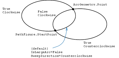
ژn“_(PathFigure.StartPoint)پCڈI“_(ArcGeometry.Point) ‚ئ ‘ب‰~‚جƒTƒCƒY Size=(Xradius,
Yradius) ‚ً—^‚¦‚ؤ‚àپCˆê”ت‚ة‚ح‰Eگ}‚ج‚و‚¤‚ة‚S‚آ‚جŒت‚ھ‚ ‚éپB
‚±‚ê‚ç‚ج‚¤‚؟‚¢‚¸‚ê‚إ‚ ‚é‚©‚ًژw’è‚·‚邽‚ك‚ةپCArcSegment‚ة‚حˆب‰؛‚ج‚Q‚آ‚جƒvƒچƒpƒeƒB‚ھ‚ ‚éپB
IsLargeArc |
True ‚ـ‚½‚ح False(ٹù’è) |
SweepDirection |
Counterclockwise(ٹù’è) ‚ـ‚½‚ح Clockwise |
پ@پ@پ@پ@
ˆب‰؛‚حپC”¼Œa50 ‚ج‰~‚جچ¶ڈم4•ھ‚ج1‚ج•”•ھ‚ً•\‚·PathGeometry‚إ‚ ‚éپB
<PathGeometry>
    <PathFigure StartPoint="0,100">
        <ArcSegment Point="100,0" Size="100,100" SweepDirection="Clockwise"></ArcSegment>
    </PathFigure>
</PathGeometry>
‚Q“_ٹش‚ةƒxƒWƒF‹بگü‚ًˆّ‚‚ة‚حپCژn“_پCڈI“_‚ج‘¼‚ةژn“_—pپCڈI“_—p‚جگ§Œن“_‚ھ•K—v‚إپCچ‡Œv‚S‚آ‚ج“_‚ًژw’è‚·‚邱‚ئ‚ة‚ب‚éپB
BezierSegment ‚جƒvƒچƒpƒeƒB Point1‚ة‚حژn“_—p‚جگ§Œن“_پCPoint2‚ة‚حڈI“_—p‚جگ§Œن“_پCPoint3‚ة‚حڈI“_‚ًژw’è‚·‚éپB
<PathGeometry>
    <PathFigure StartPoint="0,0">
        <BezierSegment Point1="0,50" Point2="150,50" Point3="100,100"></BezierSegment>
    </PathFigure>
</PathGeometry>
ژہچغ‚ة‚حپC‚±‚ج‚و‚¤‚بƒRپ[ƒh‚ًڈ‘‚¢‚ؤژg—p‚·‚邱‚ئ‚ح–إ‘½‚ة‚ب‚¢‚¾‚낤پB
‚ب‚¨پCƒxƒWƒF‹بگü‚ح’تڈي3ژںژ®‚جƒpƒ‰ƒپپ[ƒ^•\ژ¦‚إ—^‚¦‚ç‚ê‚é‚ھپCQuadraticBezierSegmnet ‚ح2ژںژ®‚ًژg‚¤‚à‚ج‚إپC
گ§Œن“_‚ئڈI“_‚ً Point1, Point2 ‚ًژw’è‚·‚éپB‚±‚جگ§Œن“_‚حپCژn“_‚ئڈI“_‚جŒX‚«‚ًژw’è‚·‚邱‚ئ‚ة‚ب‚éپB
PathGeometry ‚ة‚و‚é Path ‚حپCƒ~ƒjŒ¾Œê‚ًژg‚ء‚ؤٹب’P‚ةڈ‘‚¯‚éپB
—ل‚¦‚خپCڈم‚جLineSegment‚ًژg‚ء‚½10چs‚ج—ل‚حژں‚ج1چs‚ة‚ب‚éپB
<Path Stroke="Orange" Fill="Beige" Margin="10" Data="M 50,0 L 0,100 L 100,100 Z" />
ƒXƒyپ[ƒX‚âƒJƒ“ƒ}‚ًڈب—ھ‚µ‚ؤپCData="M50پ@0 L0پ@100 L100پ@100 Z" ‚ئڈ‘‚‚±‚ئ‚à‚إ‚«‚éپB
‚±‚ج‚و‚¤‚ةپCƒ~ƒjŒ¾Œê‚إچى‚ء‚½Geometry‚ھ StreamGeometry ‚إ‚ ‚èپC‚±‚ê‚ً’¼گع Path.Data ‚ة—^‚¦‚邱‚ئ‚ھ‚إ‚«‚éپB
| ƒRƒ}ƒ“ƒh | ˆس–، |
|---|---|
F 0 or 1 |
FillRule ƒvƒچƒpƒeƒBپBڈ‘‚ڈêچ‡‚حگو“ھ‚ةڈ‘‚پB0 ‚ح EvenOdd, 1 ‚ح NonZero ‚جˆسپB |
M x,y |
گV‚µ‚¢PathFigure‚ًچى‚èپCStartPoint‚ً(x,y)‚ة‚·‚éپB(M ‚ح Move ‚جˆس) |
L x,y |
“_(x,y)‚ض‚جLineSegment |
H x, |
x ‚ـ‚إ‚جگ…•½گüپi‰،گüپj |
V y |
y ‚ـ‚إ‚جگ‚’¼گüپiڈcگüپj |
A rX, rY, degree, IsLargeArc, Clockwise, x,y |
“_(x,y)‚ض‚جArcSegmentپB‘ب‰~‚جƒTƒCƒYپC‘ب‰~‚ج‰ٌ“]ٹpپC0 ‚ـ‚½‚ح1پC0 ‚ـ‚½‚ح1 |
C x1,y1,x2,y2,x,y |
“_(x,y)‚ض‚جBezierSegmnetپB |
Q x1,y1,x,y |
“_(x,y)‚ض‚جQuadraticBezierSegmnetپB |
S x2,y2,x,y |
“_(x,y)‚ض‚جٹٹ‚ç‚©‚ب(smooth) BezierSegmnetپBژn“_‚حپC’¼‘O‚جƒxƒWƒF‹بگü‚جڈI“_‚ھژg‚ي‚ê‚éپB‚µ‚½‚ھ‚ء‚ؤپC‘O‚جƒZƒOƒپƒ“ƒg‚ح C ‚ـ‚½‚ح S ‚إ‚ب‚‚ؤ‚ح‚ب‚ç‚ب‚¢پB |
Z |
PathFigure‚ًڈI—¹‚µپCIsClosed‚ًTrue‚ة‚·‚éپB پi•آ‚¶‚ب‚¢‚إژں‚جPathFigure‚ًچى‚é‚ئ‚«‚حپCZ‚ب‚µ‚إپCM ‚©‚çڈ‘‚¯‚خ‚و‚¢پBپj |
پ¦ƒRƒ}ƒ“ƒh‚ًڈ¬•¶ژڑ‚إڈ‘‚‚ئپCچہ•W’l‚حگâ‘خ’l‚إ‚ح‚ب‚پC‘ٹ‘خ’l‚ة‚ب‚éپB پi—لپj h 100 پ¨ ژn“_‚©‚ç‰E‚ض100ˆع“®‚µ‚½“_‚ض‚جLineSegment
پiژQچlپjPath.Data ‚إ‚ح‚ب‚پCPathGeometry.Figures ‚ًƒ~ƒjŒ¾Œê‚إڈ‘‚‚±‚ئ‚à‚إ‚«‚éپB
Geometry‚ًƒRپ[ƒh‚إڈ‘‚•û–@‚ح‚±‚؟‚ç
‚³‚ـ‚´‚ـ‚ب—v‘f‚ج Clip ƒvƒچƒpƒeƒB‚ة Geometry ‚ًژw’è‚·‚é‚ئپC‚»‚ج—v‘f‚جٹOکg‚ھGeometry‚جŒ`ڈَ‚ة‚ب‚éپB